• فارسی
  • English

SLOW SAND AND DIATOMACEOUS EARTH FILTRATION

SLOW SAND AND DIATOMACEOUS EARTH FILTRATION

Although rapid sand filters predominate, the two types of filters covered in this chapter may be effective in many applications where source water quality permits. In general, the combined costs of constructing and operating slow sand and diatomaceous earth (DE) filters may be considerably less than the cost of rapid sand filtration plants for the same capacity.
The principal mechanisms for separation of solids in all porous media filters are attachment and straining or entrapment. Because of the relationship of the somewhat large pores in rapid sand filter media compared with particulates, the primary mechanism for separation is attachment. In the case of slow sand and DE filters, however, the pore-particulate size relationship results in more substantial separation by entrapment.

During the initial operation period of slow sand filters, the separation of organic matter and other solids generates a layer of biological matter on the surface of the filter media. Once established, this layer is the predominant filtering mechanism. Solids are removed from water by a DE filter as the source water flows through a precoat layer of powderlike DE.
For all practical purposes, most solids are separated at the surface of the media in both actions. Because of the small pore size of the media, particulate separation is ideal for removing the cysts of Giardia and Cryptosporidium. In most situations, neither type of filter requires previous conditioning of the raw water.
In general, application of slow sand and DE filtration should be limited to source waters with turbidity levels less than 5 NTU. Where particulates are dominant (rather than organic matter) both types of filters may be used with water of up to 10-ntu turbidity. If either type of filter is used on water with higher turbidity, filtrate quality will generally be acceptable, but the more rapid buildup of solids on the filter results in rapid loss of head and shortened length of filter runs.
With establishment of the Stage 1 Disinfectants/Disinfection By-product Rule, filtration of surface water must achieve specified reductions in total organic content (TOC) and/or reductions in disinfection by-product levels [total trihalamethanes (TTHM) and sum of five haloacetic acids (HAA5)]. The Interim Enhanced Surface Water Treatment Rule calls for lower drinking water turbidity. This means that use of slow sand and DE filters may be limited further without the use of supplemental measures or additional treatment.

SLOW SAND FILTRATION

Slow sand filtration was the first type of porous media filtration used in water treatment.
The first recorded installations occurred in Scotland and England in the early 1800s. By the mid-1800s, legislation was passed in London, England, requiring filtration of water to be consumed. The first recorded installation of slow sand filtration facilities in the United States was in Poughkeepsie, New York, in 1872. Subsequent development of rapid rate filtration then slowed the pace of construction of slow sand plants in the United States in the early 1900s.
Around 1980, interest in using slow sand filtration was rekindled as the U.S. Environmental Protection Agency (USEPA) conducted research to develop treatment options that are simple to operate for use by small communities and that produce high-quality effluent.
Research reconfirmed that, at recommended filter rates and with appropriate media and source water quality, slow sand filtration can produce a low-turbidity effluent and can effectively remove microbiological contaminants.
When the USEPA passed the Surface Water Treatment Rule (SWTR) in 1989, further pressure was placed on communities that were not filtering surface water supplies to add filtration. Slow sand filters were rated along with rapid sand and DE filters as baseline treatment in the regulations. As a result, slow sand filtration has once again become a treatment method routinely considered in evaluating filtration options in many U.S. communities.
Abroad, it is used to provide safe drinking water to many poor or rural communities.
A major portion of the city of London water supply is treated by slow sand filtration. Renewed interest in the slow sand process has generated new research into improving treatment performance. The focus has been on expanding use of slow sand filtration in treating poorer-quality source water, especially with higher turbidity and organic content.

Slow Sand Treatment Mechanism

As its name implies, slow sand filtration is accomplished by passing water at a relatively low rate through a sand medium. The filtration rate is on the order of one-hundredth of the rate used in a typical rapid sand filter.
Because of the relatively low filter rate, head loss across the bed occurs gradually over a much longer time. Average filter run length is normally between 45 and 60 days. In some newer installations, filter run lengths in excess of 6 months and even greater than 1 year have been reported.
Slow sand filtration accomplishes its treatment primarily through biological activity, with the bulk of this activity taking place on the surface of the sand bed. A layer develops on the sand surface that is called schmutzdecke, an accumulation of organic and inorganic debris and particulate matter in which biological activity is stimulated. It has been found that some biological activity also extends deeper into the bed, where particulate removal is accomplished by bioadsorption and attachment to the sand grains.

Source Water Quality Considerations

In considering whether slow sand filtration is an appropriate treatment method, source water quality must be carefully evaluated. If source water quality data are not available, pilot testing of the source water is essential to determine the applicability of the slow sand treatment option. Below Table lists source water quality parameters with recommended limits.

Turbidity:
Both the level and type of turbidity in source water must be considered. In general, most existing slow sand plants successfully treat source water turbidity of less than 10 NTU, which is recommended for an upper limit in designing new facilities. Also of some importance is the stability of the water. Slow sand facilities operate more efficiently if source turbidity is relatively constant and generally –< 5.0 ntu. Of equal importance is the nature of particulates. Source waters that normally contain clay particulates or that pick up clay after storm events will cause problems for slow sand filters. This difficulty for slow sand filters occurs because clay penetrates deep into the bed or may even carry through the filter, causing an immediate problem of elevated filtered water turbidity and a long-term problem of filter clogging and reduced length of filter runs.

Algae:
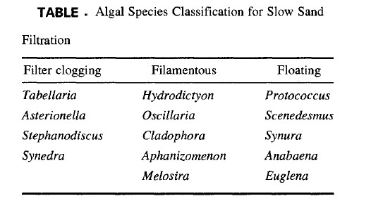
In a few instances, it has been found that the presence of certain types of algae actually enhances the filtration process by providing greater surface area for biological activity. In general, however, the presence of algae in the source water reduces filter run lengths. Table 9.2 presents a list of commonly found algal species, divided into categories related to their effect on filter performance . Filter-clogging species are detrimental to filter performance, while filamentous species may actually enhance
filter performance by providing greater surface area. Floating species would not result in direct clogging of the filter, but may shorten run lengths based on poorer-quality raw water.
Algae may be present in source water delivered to the filter and may also occur in an uncovered filter bed open to sunlight. In general, it is prudent to reduce algal content in source water to as low a level as possible to limit its effect on filter performance. Observation of algal growths, as well as identification, will aid with assessing the need for pretreatment, such as copper sulfate, and in determining when filter run lengths may be shortened. Some researchers have suggested the measurement of chlorophyll at concentrations
of 5 mg/m 3 as a limit in source water .

Color:
Color in treated water is currently categorized by USEPA as a secondary contaminant in drinking water supplies, with the focus being aesthetic concerns. As identified by Christman and Oglesby (1971), the yellow to brown color of many source waters can be the result of microbial breakdown of lignins from woody plants. True color removals of 25% or less were reported by Cleasby et al. (1984). Other research has indicated a removal range between 15% and 20% for total organic carbon. When one is evaluating the applicability of slow sand filtration for a specific source water, a review of historical trihalomethane (THM) data can reveal whether the expected low removal efficiency of aquatic organic substances by the process is a concern. Where historical color and THM data are unavailable, a sampling program can be initiated to aid in evaluating whether slow sand filtration is an appropriate treatment method.
Iron and Manganese. Slow sand filters remove iron and manganese through precipitation on the sand surface in a scaling-like action, but an upper limit of 1 mg/L of iron is suggested to avoid forming an iron precipitate that could clog filters. A similar limit for manganese would also appear to be acceptable. Collins et al. (1989) showed that iron precipitate on a slow sand filter enhanced the removal of organic precursors.
Dissolved Oxygen. The presence of dissolved oxygen in source water is critical for stimulating a healthy schmutzdecke for proper slow sand filter operation. Some slow sand plants use aeration of the water as a pretreatment. Reduction of dissolved oxygen levels commonly occurs following algal blooms, so that the importance of dissolved oxygen in the source water is another reason to control algal growth in the source. Potential problems resulting from dissolved oxygen deficiencies include tastes and odors, redissolving of precipitated metals, aesthetics, and increased chlorine demand .

Nutrients:
The proper operation of the schmutzdecke is somewhat dependent on the presence of sufficient concentrations of carbon, nitrogen, phosphorus, and sulfur. Carbon and sulfur (in sulfate form) are prevalent in most source waters. However, protected reservoir systems may have limited concentrations of nitrogen and phosphorus present.
It has been reported that, for every 1 mg of carbon removed by the schmutzdecke, 0.04 mg of nitrogen and 6/xg of phosphorus are required (Skeat, 1961). Slow sand filters have also shown the ability to remove up to 3 mg/L of ammonia from source water under the right conditions. Ammonia can be used as a source of nitrogen for the filter.

Effluent Water Quality
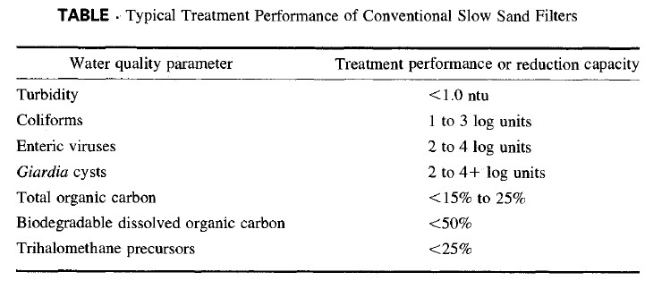
Slow sand filtration has been shown to be effective in achieving removal of Giardia and viruses. Effluent turbidities in the range of 0.1 to 0.2 ntu are typical for high-quality source waters, while turbidities of up to 1.0 ntu may be considered an upper limit. Removal of organic substances is generally in the range of 15% to 25%. Recent research has focused on improving removal because of disinfection by-product formation considerations.
Typical treatment performance of conventional slow sand filtration plants is listed in below Table Current regulations require effluent turbidities of less than 1.0 ntu. Pilot testing of the source water is recommended for determining the operational parameters and possible need for supplemental treatment to meet the established turbidity requirements. Limited data are available on removal capabilities with respect to Cryptosporidium, but research is continuing.

Design of Slow Sand Filters
The slow sand filter is relatively simple in arrangement, having only three basic elements in addition to a control system. Typical of any filter design, the complete train includes clear well storage, disinfection, and post treatment. Figure presents a cross-sectional view of a typical filter bed. Filter Box Design. The filter box contains all the filtering components of the system. These include source water storage (above the sand bed), filter sand, the underdrain system, and, in some cases, facilities for collecting wastewater generated during the cleaning process. The box floor and sides are generally constructed of concrete. Roof designs for covered filters vary and may include wood truss, steel, precast concrete, or cast in place concrete.
If the filter unit is to be covered, the height of the box must be adequate to provide for the depth of sand and support media, underdrain system, source water storage above the media, and headroom for cleaning and re sanding operations. The filter box area is determined by the unit rate of flow and required supply flow.
Slow sand filters may also be uncovered. There are currently many operating facilities that are uncovered in the U.S. Pacific Northwest, Europe, and South America. Besides lower initial cost, an advantage of uncovered filters is the far greater ease of using mechanical equipment for cleaning and maintenance. If filters are to be covered, major considerations include providing headroom for equipment during cleaning and repair, lighting, and ventilation.
A 2- to 3-ft (0.6- to 0.9-m) freeboard depth should be added over the normal water surface to provide for fluctuations in water depth within the filters without reaching ceiling height. This also provides room to install permanent lighting to improve the efficiency of cleaning and resanding. Generous headroom also allows the use of larger mechanical equipment within the filters, which can significantly reduce the time required for cleaning or resanding operations, particularly in large filters.

Filter Sand:

Guidelines for filter sand characteristics and proper media depth vary between those of the International Research Center (IRC) and the Recommended Standards for Water Works (commonly known as the l0 State Standards). The IRC manual recommends sand with an effective size of 0.15 to 0.30 mm with a uniformity coefficient between 3 and 5. The 10 State Standards recommend an effective size of 0.30 to 0.45 mm and a uniformity coefficient of <- 2.5.
A finer effective size may improve particulate removals but generally results in shorter filter run lengths. Media that are too large allow deeper bed penetration and may even result in filter breakthrough or clogging. A deeper penetration of particles in the filter bed also means that more sand must be removed during a scraping cycle. It has been suggested that a better approach is to increase the depth of the sand rather than to reduce media size if a more conservative design is desired.
Pilot testing of the process using different media sizes provides data on removals and filter run lengths and can serve as a basis for media selection.
Sand depth should generally be between 18 and 35 in. (460 and 890 mm), but some plant operators have reported satisfactory treatment with sand depth as low as 12 in. (300 mm). Most slow sand plants in the United States are designed with a minimum sand depth of 30 in. (760 mm).
If filters are cleaned by manual scraping, about 1,5 in. (1 cm) of sand is removed during the scraping. Final sand depth should be determined based on cleaning method, anticipated filter run lengths, number of scrapings desired before resanding, sand availability and expense, and impact of downtimes on plant capacity. The minimum depth before resanding should be 18 in. (460 mm).

Underdrain and Support System:

One common type of underdrain consists of a manifold and perforated laterals installed below the sand bed. Most new designs use a plastic piping system for filter underdrains. Piping material must be certified for contact with potable water. Typical lateral sizes range from 4 to 8 in. (100 to 200 mm) with the underdrain system header in the range of 8 to 16 in. (200 to 400 mm). Figure 9.2 is a view of an installation in progress of a perforated PVC underdrain system.
The underdrain system must be designed to cause minimal head loss within the system.
Head losses through the individual perforations of the laterals must be a fraction of head loss through the lateral itself to provide a balanced flow across the system. The design engineer should refer to hydraulic textbooks for guidance with respect to piping manifold system designs.
Other underdrain systems use prefabricated plastic or clay filter blocks or a false floor of concrete blocks or brick with gravel media above. Because of the large area of a slow sand filter, the prefabricated type is normally expensive to install and is used infrequently.
The hydraulics of a false floor system must be similar to those of the piped system. Gravel support media usually consist of multiple layers of graded gravel. The gravel layers are coarsest on the bottom and become finer with each layer. Gravel supports the sand, and the fine layer prevents sand from migrating down to clog underdrain openings. The 10-State Standards recommend gravel support layers similar to those required for a rapid sand installation with a media depth between 18 and 24 in. (460 and 610 mm) and gravel sizes in a range from 3A2 to 2 l& in. (2 to 64 mm) in a five-layer system.

Source Water Storage:

Source water storage is the depth and volume of water overlying the sand surface within the basin. This volume varies in different designs (between 3 and 24 h of plant capacity). As storage capacity increases, there are some benefits with respect to equalizing source water quality, sedimentation of larger particles, and even biological action within the water column itself.
The primary purpose of the water level above the sand, however, is to provide the
driving head across the filter bed. A typical terminal head loss for a slow sand filter is in the range of 4 to 5 ft (1.2 to 1.5 m). Therefore typical depths of water above the sand should range between 6 and 7 ft (1.8 and 2.1 m) to provide for the additional driving force required for head loss through the clean sand bed and through the piping systems. If a filter is to be covered, the height of the filter box above the sand is governed primarily by space requirements for cleaning and resanding, so provision of a 6- to 7-ft (1.8- to 2. l-m) depth of water can easily be accomplished.

Leave a Reply

Your email address will not be published. Required fields are marked *